Honda CR-V: DTC P0443: EVAP Canister Purge Valve Circuit Malfunction
Special Tools Required
Vacuum pump/gauge, 0-30 in.Hg, Snap-on YA4000A or equivalent, commercially available.
NOTE: Before you troubleshoot, record all freeze data and any on-board snapshot, and review the general troubleshooting information.
1. Turn the ignition switch ON (II).
2. Clear the DTC with the HDS.
3. Start the engine. Hold the engine speed at 3,000 rpm without load (in Park or neutral) until the radiator fan comes on, then let it idle.
4. Check for Temporary DTCs or DTCs with the HDS.
Is DTC P0443 indicated? YES-Go to step 5.
NO-Intermittent failure, the system is OK at this time. Check for poor connections or loose terminals at the EVAP canister purge valve and the PCM.
5. Turn the ignition switch OFF, and allow the engine to cool below 140 ºF (60 ºC).
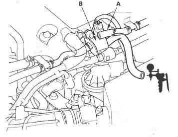
6. Disconnect the vacuum hose (A) from the purge valve (B) in the engine compartment, and connect a vacuum pump/gauge, 0-30 in.Hg, to the hose.
7. Start the engine, and let it idle.
Is there vacuum? YES-Go to step 8.
NO-Go to step 14.
8. Turn the ignition switch OFF.
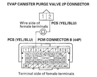
9. Disconnect the EVAP canister purge valve 2P connector.
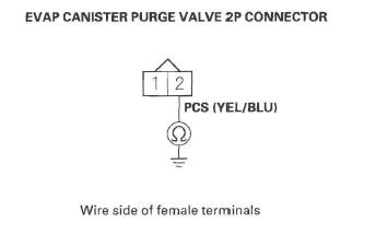
10. Check for continuity between EVAP canister purge valve 2P connector terminal No.2 and body ground.
Is there continuity? YES-Go to step 11.
NO-Go to step 23.
11. Jump the SCS line with the HDS.
12. Disconnect PCM connector B (44P).
13. Check for continuity between EVAP canister purge valve 2P connector terminal No.2 and body ground.
Is there continuity? YES-Repair short in the wire between the EVAP canister purge valve and the PCM (B3), then go to step 24.
NO-Go to step 30.
14. Turn the ignition switch OFF.
15. Disconnect the EVAP canister purge valve 2P connector.
16. Turn the ignition switch ON (II).
17. Measure voltage between EVAP canister purge valve 2P connector terminal No.1 and body ground.
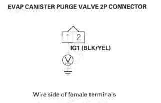
Is there battery voltage? YES-Go to step 18.
NO-Repair open in the wire between the EVAP canister purge valve and the No. 3 ALTERNATOR (10 A) fuse in the under-dash fuse/relay box, then go to step 24.
18. Turn the ignition switch OFF.
19. Jump the SCS line with the HDS.
20. Disconnect PCM connector B (44P).
21. Check for continuity between PCM connector terminal B3 and EVAP canister purge valve 2P connector terminal No.2.
Is there continuity? YES-Go to step 22.
NO-Repair open in the wire between the EVAP canister purge valve and the PCM (B3), then go to step 24.
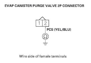
22. Measure resistance between EVAP canister purge valve 2P connector terminals No.1 and No.2.
Is there about 33 Ω at room temperature? YES-Go to step 30.
NO-Go to step 23.
23. Replace the EVAP canister purge valve.
24. Reconnect all connectors.
25. Turn the ignition switch ON (II).
26. Reset the PCM with the HDS.
27. Do the PCM idle learn procedure.
28. Check for Temporary DTCs or DTCs with the HDS.
Is DTC P0443 indicated? YES-Check for poor connections or loose terminals at the EVAP canister purge valve and the PCM, then go to step 1.
NO-Go to step 29.
29. Monitor the OBD STATUS for DTC P0443 in the DTCs MENU with the HDS.
Does the screen indicate PASSED? YES-Troubleshooting is complete. If any other Temporary DTCs or DTCs were indicated in step 28, go to the indicated DTC's troubleshooting.
NO-If the screen indicates FAILED, check for poor connections or loose terminals at the EVAP canister purge valve and the PCM, then go to step 1. If the screen indicates EXECUTING, keep idling until a result comes on. If the screen indicates OUT OF CONDITION, go to step 27.
30. Reconnect all connectors.
31. Update the PCM if it does not have the latest software, or substitute a known-good PCM.
32. Start the engine.
33. Check for Temporary DTCs or DTCs with the HDS.
Is DTC P0443 indicated? YES-Check for poor connections or loose terminals at the EVAP canister purge valve and the PCM. If the PCM was updated, substitute a known-good PCM, then go to step 32. If the PCM was substituted, go to step 1.
NO-Go to step 34.
34. Monitor the OBD STATUS for DTC P0443 in the DTCs MENU with the HDS.
Does the screen indicate PASSED? YES-If the PCM was updated, troubleshooting is complete. If the PCM was substituted, replace the original PGM. If any other Temporary DTCs or DTCs were indicated in step 33, go to the indicated DTC's troubleshooting.
NO-If the screen indicates FAILED, check for poor connections or loose terminals at the EVAP canister purge valve and the PCM. If the PCM was updated, substitute a known-good PCM, then go to step 32. If the PCM was substituted, go to step 1. If the screen indicates EXECUTING, keep idling until a result comes on. If the screen indicates OUT OF CONDITION, go to step 32.
READ NEXT:
 DTC P0451: FTP Sensor Range/Performance
Problem
DTC P0451: FTP Sensor Range/Performance
Problem
NOTE:
Before you troubleshoot, record all freeze data and any on-board
snapshot, and review the general troubleshooting information.
If DTC P2422 is stored at the same time as DTC P0451,
trouble
DTC P0453: FTP Sensor Circuit High Voltage
NOTE: Before you troubleshoot, record all freeze data and any on-board
snapshot, and review the general troubleshooting information.
1. Turn the ignition switch ON (II).
2. Clear the DTC with the H
DTC P0455/P0456: EVAP System Large Leak
Detected/Very Small Leak Detected
DTC P0455: EVAP System Large Leak
Detected
DTC P0456: EVAP System Very Small Leak
Detected
NOTICE
The fuel system is designed to allow specified
maximum vacuum and pressure conditions. Do not
deviate
SEE MORE:
Power Mirrors
Component Location Index
POWER MIRRORS/POWER MIRROR DEFOGGERS
AUXILIARY
UNDER-HOOD
RELAY BOX
POWER MIRROR
DEFOGGER RELAY
REAR WINDOW DEFOGGER SWITCH/
MIRROR DEFOGGER SWITCH
POWER MIRROR SWITCH
Circuit Diagram
Function Test
1. Remove the power mirror switch.
2. Disconnect the 13P co
How Your Side Curtain Airbags Work
In a Side Impact
In a moderate to severe side impact,
sensors will detect rapid acceleration
and signal the control unit to
instantly inflate the side curtain
airbag.
If the impact is on the passenger’s
side, the passenger’s side curtain
airbag will inflate even if there are no
