Honda CR-V: A/C Signal Circuit Troubleshooting
NOTE:
- Use this troubleshooting procedure if the A/C compressor, the A/C condenser fan, and radiator fan are inoperative.
- Before doing symptom troubleshooting, check for and resolve any powertrain DTCs.
1. Turn the ignition switch ON (II).
2. Check if the blower motor operates at all speeds.
Does the blower motor operate at all speeds? YES-Go to step 3.
NO-Repair the problem in the blower motor circuit. 3. Turn the ignition switch OFF.
4. Disconnect the HVAC control unit 28P connector.
5. Turn the ignition switch ON (II).
6. Measure the voltage between the HVAC control unit 28P connector terminal No. 10 and body ground.
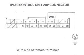
Is there voltage? YES-Go to step 13.
NO-Go to step 7.
7. Turn the ignition switch OFF.
8. Disconnect the A/C compressor clutch 3P connector.
9. Turn the ignition switch ON (II).
10. Measure the voltage between the A/C compressor clutch 3P connector terminal No.1 and body ground.
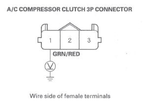
Is there battery voltage? YES-Go to step 11.
NO-Repair open in the wire between the A/C compressor and the MICU. If the wire is OK, substitute a known-good MICU and recheck. If the symptom goes away, replace the original MICU.
11. Test the A/C compressor thermal protector.
Is the A/C compressor thermal protector OK? YES-Go to step 12.
NO-Replace the A/C compressor thermal protector.
12. Check for continuity between the HVAC control unit 28P connector terminal No. 10 and the A/C compressor clutch 3P connector terminal No.2.
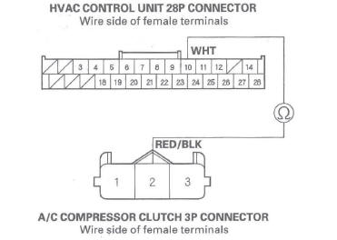
Is there continuity? YES-Check for loose wires or poor connections at the HVAC control unit 28P connector and at the A/C compressor clutch 3P connector.
NO-Repair open in the wire between the HVAC control unit and A/C compressor.
13. Turn the ignition switch OFF.
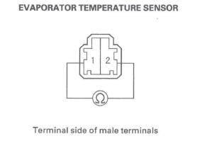
14. Measure the evaporator temperature sensor resistance between the HVAC control unit 28P connector terminals No. 9 and No. 19.
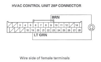
Is resistance less than 24 k Ω ? YES-Check for loose wires or poor connections at the HVAC control unit 28P connector. If the connections are good, substitute a known-good HVAC control unit and recheck. If the symptom goes away, replace the original HVAC control unit.
NO-Test the evaporator temperature sensor.
Evaporator Temperature Sensor Test
1. Remove the evaporator core and the evaporator temperature sensor.
2. Dip the sensor in ice water, and measure the resistance between its terminals.
3. Then pour warm water on the sensor, and check for a change in resistance.
4. Compare the resistance readings with the specifications shown in the graph; the resistance should be within the specifications.
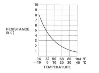
5. If the resistance is not as specified, replace the evaporator temperature sensor.
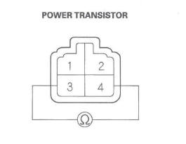
Power Transistor Test
1. Remove the passenger's dashboard undercover.
2. Disconnect the 4P connector from the power transistor.
3. Measure the resistance between the No.3 and No.4 terminals of the power transistor. It should be about 1.5 k Ω.
- If the resistance is within the specifications, go to step 4.
- If the resistance is not within the specifications, replace the power transistor.
NOTE: Also check the blower motor. Power transistor failuer can be caused by a defective blower motor.
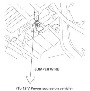
4. Carefully release the lock tab on the No.1 terminal (RED) (A) in the 4P connector, then remove the terminal and insulate it from body ground.
5. Reconnect the 4P connector to the power transistor.
6. Make sure the RED wire is completely isolated, then supply 12 V to the No. 1 cavity with a jumper wire.
7. Turn the ignition switch ON (II), and check that the blower motor runs.
- If the blower motor does not run, replace the
power transistor.
NOTE: A faulty blower motor can cause the power transistor to fail. If the power transistor is replaced, also check the blower motor for binding, and replace it if necessary.
- If the blower motor runs, the power transistor is OK.
Air Mix Control Motor Test
NOTE: Before testing, check for HVAC DTCs.
1. Disconnect the 7P connector from the air mix control motor.
NOTICE
Incorrectly applying power and ground to the air mix control motor will damage it.
Follow the instructions carefully.
2. Connect battery power to the No.1 terminal of the air mix control motor, and ground the No.2 terminal; the air mix control motor should run, and stop at Max Hot. If it doesn't, reverse the connections; the air mix control motor should run, and stop at Max Cool. When the air mix control motor stops running, disconnect battery power immediately.
3. If the air mix control motor did not run in step 2, remove it, then check the air mix control linkage and door for smooth movement.
- If the linkage and door move smoothly, replace the air mix control motor.
- If the linkage or door sticks or binds, repair them as needed.
- If the air mix control motor runs smoothly, go to step 4.
4. Measure the resistance between the No.5 and No.7 terminals. It should be between 4.2 to 7.8 k Ω.
5. Reconnect the air mix control motor 7P connector, then turn the ignition switch ON (II).
6. Using the backprobe set, measure the voltage between the No.3 and No.7 terminals.
Max Cool: about 0.5 V
Max Hot: about 4.5 V
7. If either the resistance or voltage readings are not as specified, replace the air mix control motor.
Air Mix Control Motor Replacement
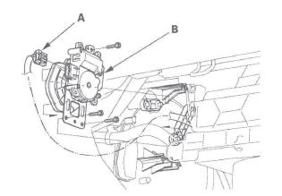
1. Disconnect the 7P connector (A) from the air mix control motor (B). Remove the self-tapping screws and the air mix control motor from the heater unit.
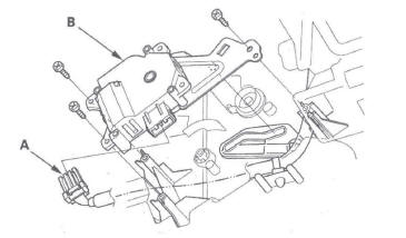
2. Install the motor in the reverse order of removal.
Make sure the pin on the motor is properly engaged with the linkage. After installation, make sure the motor runs smoothly.
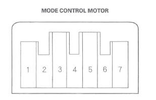
Mode Control Motor Test
NOTE: Before testing, check for HVAC DTCs.
1. Disconnect the 7P connector from the mode control motor.
NOTICE
Incorrectly applying power and ground to the mode control motor will damage it.
Follow the instructions carefully.
2. Connect battery power to the No.1 terminal of the mode control motor, and ground the No.2 terminal; the mode control motor should run smoothly, and stop at Vent. If it doesn't, reverse the connections; the mode control motor should run smoothly, and stop at Defrost. When the mode control motor stops running, disconnect battery power immediately.
3. If the mode control motor did not run in step 2, remove it, then check the mode control linkage and doors for smooth movement.
- If the linkage and doors move smoothly, replace the mode control motor.
- If the linkage or doors stick or bind, repair them as needed.
- If the mode control motor runs smoothly, go to step 4.
4. Use a digital multi meter with an output of 1 mA or less at the 20 k Ω range. With the mode control motor running as in step 2, check for continuity between the No.3, 4, 5, and 6 terminals and the No.7 terminal individually. There should be continuity for a moment at each terminal as the motor moves past the switch's terminal.
5. If there is no continuity for a moment at each terminal, replace the mode control motor.
Mode Control Motor Replacement
1. Remove the glove box.
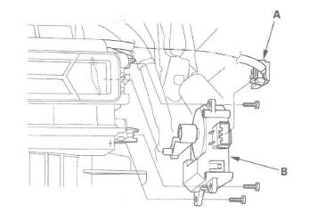
2. Remove the wire harness clips (A), the self-tapping screws, and the passenger's heater duct (B).
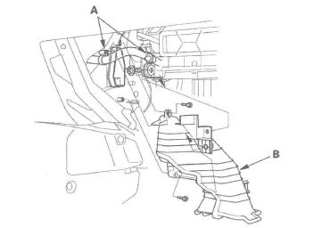
3. Disconnect the 7P connector (A) from the mode control motor (B). Remove the self-tapping screws and the mode control motor from the heater unit.
4. Install the motor in the reverse order of removal.
Make sure the pin on the motor is properly engaged with the linkage. After installation, make sure the motor runs smoothly.
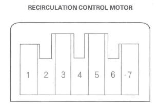
Recirculation Control Motor Test
NOTE: Before testing, check for HVAC DTCs.
1. Disconnect the 7P connector from the recirculation control motor.
NOTICE
Incorrectly applying power and ground to the recirculation control motor will damage it.
Follow the instructions carefully.
2. Connect battery power to the No.1 terminal of the recirculation control motor, and ground the No.5 and No.7 terminals; the recirculation control motor should run smoothly. To avoid damaging the recirculation control motor, do not reverse power and ground. Disconnect the No.5 or No.7 terminals from ground; the recirculation control motor should stop at Fresh (when the No.5 terminal is disconnected) or Recirculate (when the No.7 terminal is disconnected). Don't cycle the recirculation control motor for a long time.
3. If the recirculation control motor did not run in step 2, remove it, then check the recirculation control linkage and door for smooth movement.
- If the linkage and door move smoothly, replace the recirculation control motor.
- If the linkage or door stick or bind, repair them as needed.
Recirculation Control Motor Replacement
1. Remove the glove box.
2. Disconnect the 7P connector (A) from the recirculation control motor (B). Remove the self-tapping screws and the recirculation control motor from the blower unit.
3. Install the motor in the reverse order of removal.
Make sure the pin on the motor is properly engaged with the linkage. After installation, make sure the motor runs smoothly.
HVAC Control Unit Removal/Installation
1. Move the shift lever to position 1.
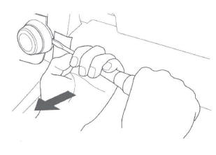
2. Place protective tape (A) on both sides of the dashboard next to the HVAC control unit.
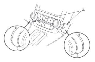
3. Insert a flat-tip screwdriver in the groove on each side, then pull straight out on both screwdriver shafts.
NOTE: Do not pry with the flat-tip screwdrivers.
4. Remove the HVAC control unit (A). Disconnect the connector (B), then remove the harness clip (C).
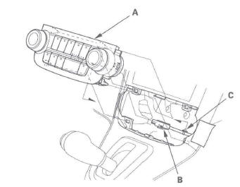
5. Install the control panel in the reverse order of removal. After installation, operate the various functions to make sure they work properly.
6. Run the self-diagnosis function to confirm that there are no problem in the system.
Dust and Pollen Filter Replacement
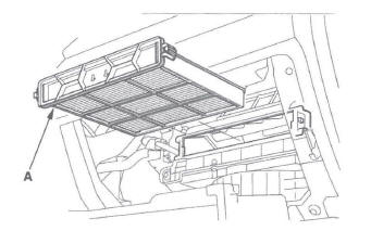
1. Open the glove box. Remove the glove box stop on right side, then let the glove box hang down.
2. Remove the dust and pollen filter assembly (A) from the evaporator.
3. Remove the filter (A) from the housing (B), and replace the filter.
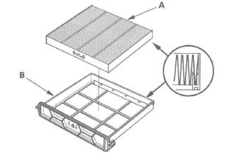
4. Install the filter in the reverse order of removal.
Make sure that there is no air leaking out of the blower unit.
READ NEXT:
 Blower Unit
Removal/Installation
Blower Unit
Removal/Installation
1. Remove the glove box.
2. Disconnect the connector (A), then remove the
connector clip (B), the wire harness clips (C), the
bolts, and the glove box frame (D).
3. Cut the plastic cross brace (A) i
Evaporator Core
Replacement
1. Recover the refrigerant with a recovery/recycling/ charging station.
2. Remove the bolt from the A/C line clamp, and
remove the receiver line (A) from the clips (B).
3. Remove the nut, then disco
Heater Unit/Core
Replacement
SRS components are located in this area. Review the
SRS component locations, and the
precautions and procedures before
doing repairs or service.
1. Make sure you have anti-theft codes for the audio
sy
SEE MORE:
Front and Rear Suspension
Special Tools
Strut Nut Adapter
Universal Eyelet
Hub Dis/Assembly Tool
Attachment, 40 mm
Ball Joint Remover, 32 mm
Ball Joint Remover, 28 mm
Ball Joint Thread Protector, 14 mm
Attachment, 72 x 75 mm
Driver
Attachment, 96 mm
Support Base
Component Location Index
Front Suspension
STAB
Information Display
As an incoming call notification, you
will see the following display:
A notification that there is an
incoming call, or HFL is in use, will
appear on the navigation screen
when the audio system is on.
When there is an incoming call, or
HFL is in use, ‘‘HFL’’ will appear at
