Honda CR-V: Cable Reel Replacement
Removal
1. Make sure the front wheels are aligned straight ahead.
2. Disconnect the negative cable from the battery, and wait at least 3 minutes.
3. Remove the driver's airbag.
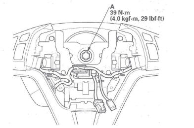
4. Disconnect the connector (A) from the cable reel, then remove the steering wheel bolt (B).
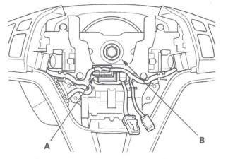
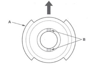
5. Confirm that the front wheels point straight ahead, then remove the steering wheel with a steering wheel puller (see step 6).
Do not tap on the steering wheel or steering column shaft when removing the steering wheel.
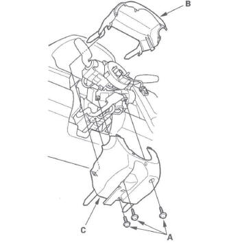
6. Remove the driver's dashboard undercover.
7. Remove the column cover screws (A), then remove the column covers (B, C).
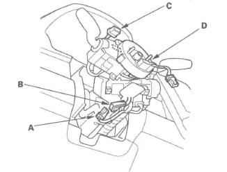
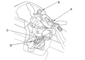
8. Disconnect the dashboard wire harness 4P connector (A) from the cable reel 4P connector (B), then disconnect the dashboard wire harness 13P or 5P connector (C) from the cable reel (D).
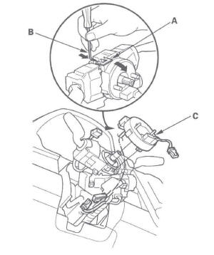
9. Release the lock tab (A) under the cable reel connector with a 90 º hook shaped tool (B). Slide the tool below the cable reel connector just above the lock tab. Release the lower lock tab (C), and slide the cable reel off the column.
Installation
1. Before installing the steering wheel, align the front wheels straight ahead.
2. If not already done, disconnect the negative cable from the battery, and wait at least 3 minutes.
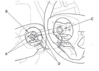
3. Set the turn signal canceling sleeve (A) so that the projections (B) are aligned vertically.
4. Carefully install the cable reel (A) on the steering column shaft. Then connect 13P or 5P connector (B) to the cable reel, and connect the 4P connector (C) to the dashboard wire harness 4P connector (D).
5. Install the steering column covers.
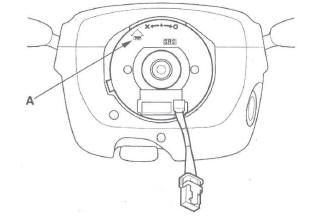
6. If necessary, center the cable reel (New replacement cable reels come centered.). Do this by first rotating the cable reel clockwise until it stops. Then rotate it counterclockwise (about three turns) until the arrow mark (A) on the cable reel label points straight up.
7. Position the two tabs (A) of the turn signal canceling sleeve (B) as shown, and install the steering wheel on to the steering column shaft, making sure the steering wheel hub (C) engages the pins (D) of the cable reel and tabs of the turn signal canceling sleeve. Do not tap on the steering wheel or steering column shaft when installing the steering wheel.
8. Install a new steering wheel bolt (A), then reconnect the connectors.
9. Install the driver's airbag.
10. Reconnect the negative cable to the battery.
11. After installing the cable reel, confirm proper system operation:
- Turn the ignition switch ON (II); the SRS indicator should come on for about 6 seconds and then go off.
- After the SRS indicator has turned off, turn the steering wheel fully left and right to confirm the SRS indicator does not come on.
- Make sure the horn works.
- Make sure the cruise control buttons work.
- Make sure the steering shift switches work.
SRS Unit Replacement
Removal
NOTE: If you are only disconnecting SRS unit connector A, skip step 2.
1. Disconnect the negative cable from the battery, and wait at least 3 minutes before beginning work.
2. Disconnect both seat belt tensioner connectors (see step 7) and both seat belt buckle tensioner connectors (see step 8).
3. Remove the dashboard center lower cover.
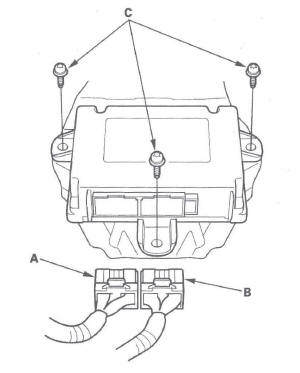
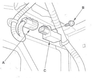
4. Disconnect the connector A, connector B, and remove the TORX bolts (C), then pull out the SRS unit.
Installation
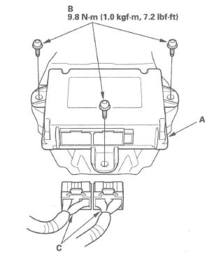
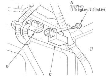
1. Install the new SRS unit (A) with new TORX bolts (B), then connect the connectors (C) to the SRS unit; push them into position until they click.
NOTE: Be sure the SRS unit is sitting squarely against its bracket before torquing the TORX bolts.
2. Reconnect both seat belt tensioner connectors (see step 7) and seat belt buckle tensioner connector (see step 8).
3. Reconnect the negative cable to the battery.
4. After installing the SRS unit, confirm proper system operation: Turn the ignition switch ON (II); the SRS indicator should come on for about 6 seconds and then go off.
5. Reinstall all removed parts.
Side Impact Sensor (First) Replacement
NOTE: Review the seat replacement procedure before doing repairs or service.
Removal
1. Disconnect the negative cable from the battery, and wait at least 3 minutes before beginning work.
2. Disconnect the appropriate side airbag 2P connector (see step 4).
3. Remove the front seat assembly.
4. Remove the lower B-pillar lower trim.
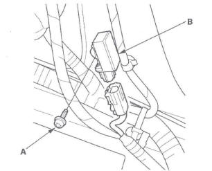
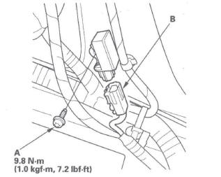
5. Disconnect the floor wire harness 2P connector from the side impact sensor (first).
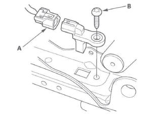
6. Using a TORX T30 bit, remove the TORX bolt (A), then remove the side impact sensor (first) (B).
Installation
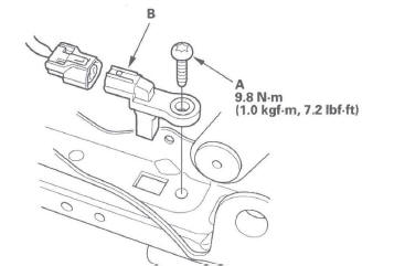
1. Install the new side impact sensor (first) with the TORX bolt (A), then connect the floor wire harness 2P connector (B) to the side impact sensor (first).
2. Reconnect the negative cable to the battery.
3. After installing the side impact sensor (first) confirm proper system operation: Turn the ignition switch ON (II); the SRS indicator should come on for about 6 seconds and then go off.
4. Reinstall all removed parts.
Side Impact Sensor (Second) Replacement
Removal
1. Disconnect the negative cable from the battery, and wait at least 3 minutes before beginning work.
2. Disconnect the appropriate side curtain airbag 2P connector (see step 5).
3. Remove the quarter piller glass trim.
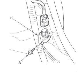
4. Disconnect the side wire harness 2P connector from the side impact sensor (second).
5. Using a TORX T30 bit, remove the TORX bolt (A), then remove the side impact sensor (second) (B).
Installation
1. Install the new side impact sensor (second) with the TORX bolt (A), then connect floor wire harness 2P connector (B) to the side impact sensor (second).
2. Reconnect the negative cable to the battery.
3. After installing the side impact sensor (second), confirm proper system operation: Turn the ignition switch ON (II); the SRS indicator should come on for about 6 seconds and then go off.
4. Reinstall all removed parts.
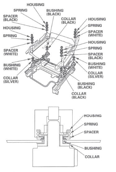
Front Passenger's Weight Sensor Replacement
Removal
NOTE: Removal of the front passenger's weight sensors must be performed according to the precautions/ procedures described at the beginning of the SRS section.
1. Disconnect the negative cable from the battery, and wait at least 3 minutes before beginning work.
2. Remove the front passenger's seat assembly section.
3. Remove the cushion cover/pad from the seat cushion frame.
4. Using a TORX E18 socket, remove the TORX nuts (A) attaching the seat track (B) to the weight sensors (C).
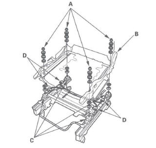
5. Disconnect the sensor connectors (D) from the seat weight sensor, then remove the front passenger's weight sensors.
Installation
NOTE:
- Be sure to install the harness wires so they are not pinched or interfering with other parts.
- A spacer has front and back faces. Be sure to install the spacer correctly.
1. Install the new front passenger's weight sensors under the seat track.
2. When tightening the TORX nuts (A), begin with 1, and tighten them in a crisscross pattern in two or more steps.
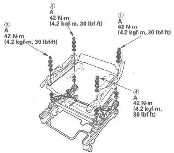
3. Torque the TORX nuts in the sequence shown in two or more steps.
4. Reassemble the front passenger's seat cushion cover/pad.
5. Reinstall the front passenger's seat.
6. Reconnect the negative cable to the battery.
7. Calibrate the ODS unit.
8. After installing the front passenger's weight sensors, confirm proper system operation: Turn the ignition switch ON (II); the SRS indicator should come for about 6 seconds and then go off.
ODS Unit Replacement
NOTE: Review the seat replacement procedure before doing repairs or service.
Removal
1. Disconnect the negative cable from the battery, and wait at least 3 minutes before beginning work.
2. Disconnect the front passenger's side airbag 2P connector (see step 3).
3. Remove the passenger's seat assembly and seat-back cover.
4. Disconnect the ODS unit 18P connector (A) and sensor connectors (B) from the ODS unit (C).
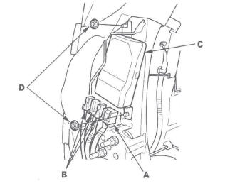
5. Remove the two nuts (D) and the ODS unit.
Installation
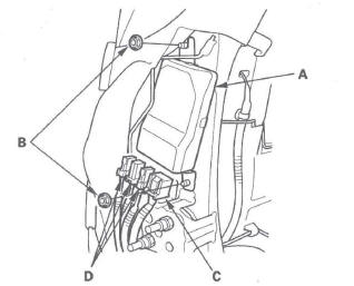
1. Place the new ODS unit (A) on the seat-back frame.
Tighten the two nuts (B), and connect the ODS unit 18P connector (C) and sensor connectors (D) to the ODS unit.
2. Install the seat-back cover in the reverse order of removal.
3. Install the seat assembly, then connect the side airbag 2P connector.
4. Reconnect the negative cable to the battery.
5. Set the seat-back in the normal position, and make sure there is nothing on the front passenger's seat.
6. Initialize the ODS unit.
7. After installing the ODS unit, confirm proper system operation: Turn the ignition switch ON (II); the SRS indicator should come on for about 6 seconds and then go off.
Front Impact Sensor Replacement
Removal
1. Disconnect the negative cable from the battery, and wait at least 3 minutes before beginning work.
2. Disconnect the driver's airbag 4P connector- (see step 2), the front passenger's airbag 4P connector (see step 3), both seat belt tensioner 4P connectors (see step 7), and both seat belt buckle tensioner 2P connectors (see step 8).
3. Remove the front inner fender.
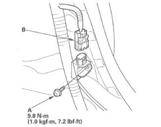
4. Disconnect the engine compartment wire harness 2P connector (A). Using a TORX T30 bit, remove the TORX bolt (B), then remove the front impact sensor (C).
Installation
1. Install the new front impact sensor with a new TORX bolt (A), then connect the engine compartment wire harness 2P connector (B) to the front impact sensor (C).
2. Reconnect the negative cable to the battery.
3. After installing the front impact sensor, confirm proper system operation: Turn the ignition switch ON (II); the SRS indicator should come on for about 6 seconds and then go off.
4. Reinstall all removed parts.
Driver's Seat Position Sensor Replacement
Removal
NOTE:
- Removal of the driver's seat position sensor must be performed according to the precautions/procedures described at the beginning of SRS section.
- Do not turn the ignition switch ON (II), and do not connect the battery cable while removing the driver's seat position sensor.
1. Disconnect the negative cable from the battery, and wait at least 3 minutes before beginning work.
2. Disconnect the driver's airbag 4P connector (see step 2).
3. Remove the driver's seat assembly.
4. Disconnect the seat position sensor harness 2P connector (A) from the driver's seat position sensor.
5. Using a TORX T30 bit, remove the TORX bolt (B), then remove the driver's seat position sensor.
Installation
NOTE:
- Be sure to install the harness so it does not pinched or interfere with other parts.
- Do not turn the ignition switch ON (II), and do not connect the battery cable while installing the driver's seat position sensor.
- After installing the driver's seat position sensor, make sure it is clean. Keep it away from dust.
1. Install the new driver's seat position sensor with a TORX bolt (A), then connect the floor wire harness or seat position sensor harness 2P connector to the driver's seat position sensor (B).
2. Install the driver's seat assembly.
3. Reconnect the negative cable to the battery.
4. Check the operation of the driver's seat position sensor with the HDS.
Passenger's Airbag Cutoff Indicator Illumination Bulb Test
1. Remove the dashboard center vent panel.
2. Disconnect the 6P connector (A) from the passenger's airbag cutoff indicator (B).
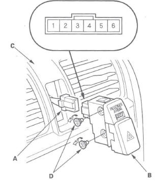
3. Push out the passenger's airbag cutoff indicator from behind the center vent panel (C).
4. Check for continuity between the No.3 and No.4 terminals of the indicator. If there is no continuity, replace the bulb (D).
NOTE: Both illumination bulbs are connected in parallel. If there is continuity, remove the upper, hazard switch illumination bulb, and recheck for continuity. If there is no continuity, replace the lower, passenger's airbag cutoff indicator illumination bulb.
5. Reinstall the parts in the reverse order of removal.
Restraints
Special Tools
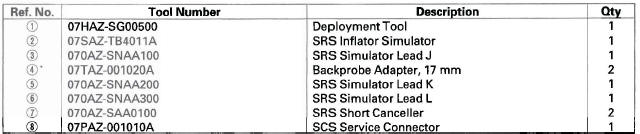
* : Use With the stacking patch cords from T/N 07SAZ-001000A, Backprobe Set.
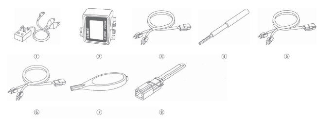
- Deployment Tool
- SRS Inflator Simulator
- SRS Simulator Lead J
- Backprobe Adapter, 17 mm
- SRS Simulator Lead K
- SRS Simulator Lead L
- SRS Short Canceller
- SCS Service Connector