Honda CR-V: manuals and service guides

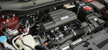
Honda CR-V is more powerful, more stylish and more comfortable than the previous-generation models. Its new suspension geometry delivers an improved ride and better, more responsive handling. Third-generation Honda CR-V is likely to appeal to buyers of all ages and both genders, Honda's target audience for its redesigned small SUV is women in their early 30s with a child under two. And when you drive the new CR-V, it's obvious the company had this audience in mind from the very beginning.

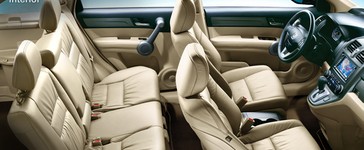
In sculpting the CR-V’s sultry shape, we focused on modern lines, aerodynamics and a meticulous attention to detail. From any angle – up close or at a distance – you’ll be captivated every time you view it. The CR-V is ready to play wherever your life takes you. whether pulling into a drive-through or up to a club valet, it’s equally at home. As you’re soon to find out, good impressions are its specialty.
Honda CR-V (2006–2011) Owner's Manual
Owners manual for third generation Honda CR-V. This owner’s manual covers all models of the CR-V. You may find descriptions of equipment and features that are not on your particular vehicle. To help you make informed decisions about safety, we have provided operating procedures and other information on labels and in this manual. This information alerts you to potential hazards that could hurt you or others.